Categories
Uncategorized

New Facility Progress #11

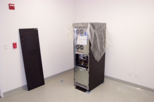
DCP_2616

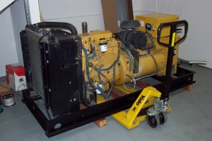
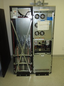
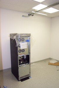
A generator awaiting installation.

DCP_2627

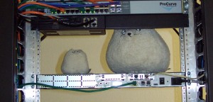
The “rollers”, our unofficial mascots that take residence in the server room on top of a router.

DCP_2638[1] DCP_2637

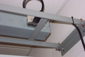
Detail view of the electrical outlet installation. The smallest circuit we offer is 20A at 208VAC in single phase or three phase, but we can easily provide multiple 20 and 30 amp circuits per rack in single phase or three phase for high density racks. (We do not offer 120VAC circuits.)

DCP_2631

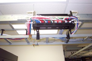
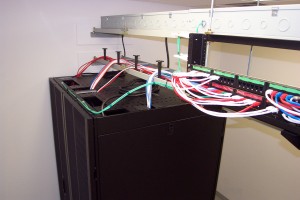
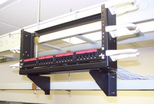
Detail view of the patchrack. By keeping patch panels out of the racks and using the overhead ladder to route them where they need to be we increase server density and eliminate wasted ports. If high port density per rack is required, top-of-rack switching would be used.

DCP_2640

Detailed view of the overhead area. Even though you can’t see this without a ladder, we like to keep everything in order.

DCP_2632

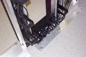
Power cord cable management for the router and switch racks.

DCP_2635

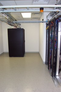
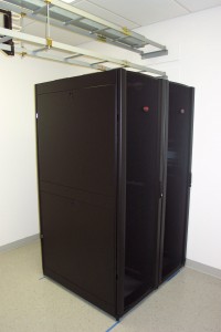
A view of the server room. What was spread out over five racks in the old facility was consolidated into two racks (not counting the two-post racks to the right). The extra space will be offered for colocations and dedicated servers and we will continue installing racks to fill the room. The yellow cables hanging out of the wire management on the right indicate temporary cabling.

Categories
Uncategorized

New Facility Progress #10

We’re on the eve of the move and this is probably the last new facility update before actually moving in. Verizon is still missing in action, but we’re going ahead without them since it’s clear that it isn’t getting resolved anytime soon. We would like to thank Sprint for being patient with us since they were ready to hot cut back in August and we kept delaying to try to resolve things with Verizon.

PA060006-alt

Final layout of a UPS and its battery cabinet before wiring. Three of these complete units will fit into our UPS electrical room (up to 4 supported) to act as one parallel redundant unit.

PA070005

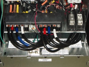
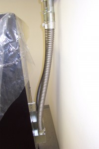
A close up of the UPS wiring. The cable is 1/0 AWG.

DCP_2605

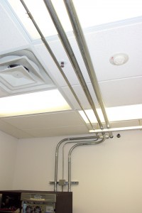
Some of the overhead piping in the UPS electrical room.

PA070006

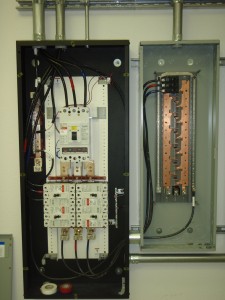
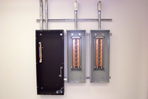
One of the two distribution panels for the server room (right) and the UPS paralleling panelboard (left).

PA070001

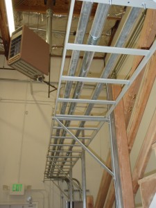
Overhead piping between the UPS electrical room to the panelboard that supports it. The panelboard is connected to our generator automatic transfer switch allowing it to be fed by utility power or generator power. As you can see, this is in the warehouse portion of the facility, which will house the generator.

DCP_2600

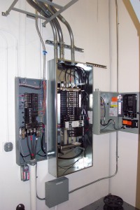
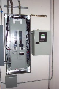
The original load center (left), the new panelboard for our stuff (middle), and our automatic generator transfer switch (right).

DCP_2608

The panelboard with its dead front installed, wiring cleaned up, and the transfer switch after turning the power on for the first time. The generator will be installed within the week and piped to the connectors on top of the transfer switch. Wiring the generator is as simple as connecting it to the “emergency” contacts inside the transfer switch after the not so simple process of moving a very heavy diesel engine.

The next update will be after the major move of circuits and equipment this weekend. There’s still plenty for us to do before we can consider it done and take a break, so stay tuned!

Categories
Uncategorized

New Facility Progress #9

Today the distribution panels were mounted and the conduit attached to the UPS.

DCP_2580 DCP_2581

All of the conduit and panel installations are just about done, at which point we’ll be waiting for a custom 400A panelboard to arrive in order to finish it out and power everything up.

Categories
Uncategorized

New Facility Progress #8

We have a few pictures we’d like to share for this update. We’ve moved UPS #1 into position in the electrical room where it awaits its electrical connections.

DCP_2569 DCP_2571

As before, the blue tape on the floor marks equipment footprints and helps us position everything with appropriate clearances. The unit is heavy enough that it’s indented the composite tile floor where it’s sitting, however the slab underneath is 14″ fiber reinforced concrete intended for industrial loads, so we don’t have to worry about about equipment point loads in here or in the server room. It also makes an excellent mounting surface for concrete anchors.

DCP_2572

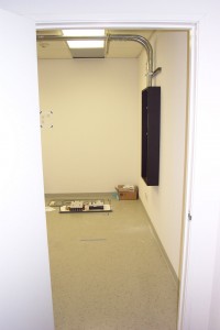
This is a view into the electrical room through the door. UPS #1 is immediately to the left, while units #2 and #3 will be placed in a clockwise manner (which you can see in the diagram taped to the far wall). The black box is the paralleling panel board with its internals laying on the floor. The breakers and bus bars were removed to prevent damage and drastically reduce weight (it’s 200 pounds fully assembled) for installation. The empty space to the right will contain two distribution panels to be installed on Monday.

Moving on to the server room, we’ve finished installation of the overhead wireways and started to temporarily place some racks and panels to get a feel for the installation. So far everything is lining up exactly as planned.

DCP_2573

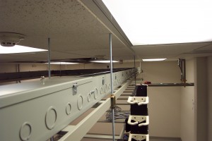
These are the hinge-top wireways that will contain all of the electrical wiring in the server room. Rack outlets will be attached on the opposing side. You can also see the conduit through the ceiling that connects to the telco room upstairs. What’s that black thing bolted to the side of the lower ladder rack, you ask?

DCP_2577

This nifty piece of hardware is called a “patch rack”. It’s basically a 4U mini rack that we’re using to place permanently wired patch panels at strategic locations in the overhead space above the racks. We can do this because we operate a closed floor, escorted access only facility. This allows us to do little things like this to give our customers extra space to work with in their racks rather than taking it up with our equipment.

DCP_2574

And finally, it wouldn’t be much of a photo update without a picture of some racks. These are the four post enclosed cabinets we’re using as standard equipment. The two in this picture are in the planned position right on their blue tape markers and will eventually be leveled and bolted to the floor when the time comes. You can see the patch rack and hinge-top wireways in the overhead ladder racks.

Categories
Uncategorized

New Facility Progress #7

The ceiling in the back where the electrical service entrance is 25 feet, so we installed this ladder rack to bring it down to 9 feet in order to ease installation and future additions. It also drastically reduces the installed wire footage.

P9210018 P9210023

At the top of the frame you’ll see a set of three conduits on a rack secured to the wall – those carry the fiber optic lines, electrical, and copper to the telco room upstairs (anything secured to channel strut is ours). Those were a chore to install and required the use of a scissor lift, something we’d prefer to avoid for the multiple heavy gauge runs of the UPS mains, bypasses, and generator feed. We’ll be adding a fourth conduit to the ceiling run for the server room air conditioner – which will also be housed on the second floor – as soon as we can get the lift again.

The unpainted section on the concrete wall used to house a large haphazard phone board (which we promptly removed) and will be the future home to our additional electrical service panels to support the UPS room and generator transfer switch.